Added later after many falcate classicals: I was completely off in my original analysis of falcate brace height. I now set the main falcate braces at 10.5–11.5 mm, with the secondary falcates at 8 mm. A classical guitar wants a higher top resonance than a steel‑string and has a thinner top, hence the taller braces. My guitars do not have a lower transverse brace. If building a guitar with an open lower transverse brace, a height of 6 mm would be appropriate.
This is the first classical guitar I've built with carbon fiber reinforced falcate bracing. The design relies heavily on the Gore/Gilet Contemporary Acoustic Design and Build books. This guitar isn't being built for anyone, so there's no time constraint and no fear of failure — a good mindset for pushing into new territory.
The starting point: I've already built a medium-sized Gore Falcate steel string, and its body length nearly matches the Hauser 37 mold I have. The Hauser has a narrower lower bout but the SS falcate bracing pattern still fits, and both are 12-fret to the body with similar scale lengths, so the bridge placement is close and the bending and layup molds I built can be reused.
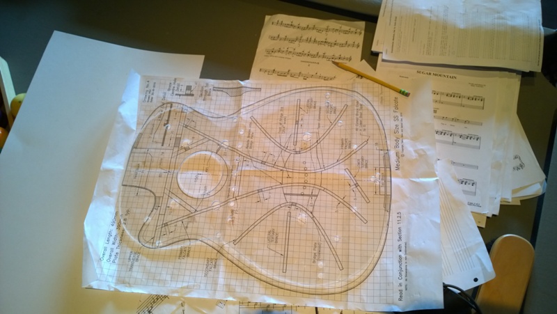
Falcate bracing pattern on the Hauser 37 body — adapted from the medium-sized Gore SS guitar
Design Reasoning — Brace HeightFrom section 4.4 of the Design book: the flexural rigidity of the Gore falcate medium SS is about 40 Nm², and the falcate classical is about 20 Nm² — matching the 50% difference in string load between steel string and classical. Using vibrational stiffness 60 in equation 4.5-7 gives a 20% reduction in top thickness vs my SS target. A 20% thinner plate is a 50% reduction in plate stiffness but only about a 10–15% reduction in braced-top stiffness once the CF and braces are considered. To close the gap toward the 50% flexural rigidity target, I decided to reduce the main falcate braces from 7mm to 6mm — roughly a 40% reduction in brace stiffness. My target top frequency: 190 Hz.
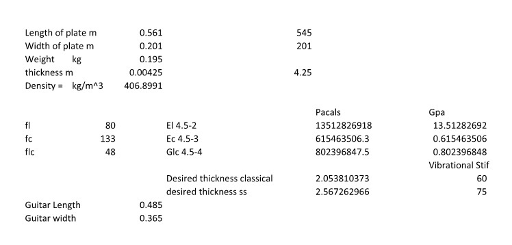
Top thickness calculation — vibrational stiffness value 60 for classical guitar (equation 4.5-7), resulting in 20% thinner plate than SS
January 26th, 2015 — Rosette & Back Strip
A week out of the shop with sciatica — scary since I normally have no back pain. Getting better now. I used a hybrid rosette: a nicely made pre-made classical rosette with mosaic tiled purfling rings inside and out, then routed out the center for an Australian Blackwood ring. Came out OK. I'm planning a proper classical mosaic rosette eventually, but this works for now.
Australian Blackwood bindings with BWB purfling throughout. For the back strip I scored the channel lines deeply with a scalpel first — with the channels scored deep I could rout close to the line and the thin remaining strip mostly came out during routing. Cleanest channel I've made. Also got to try out my new old #8 plane when jointing the plates.
.jpg)
BWB back strip inlaid — scalpel scoring the channel lines first gave the cleanest result yet
January 26th, 2015 — Back Braces
I used the Gore/Gilet technique for shaping back braces — table saw to dimension the stock, then router table to profile the shape. Much faster than hand-shaping. The jig is a board with a rabbet the same width as the brace and two screws centered in the rabbet. I screw the brace stock in, route one side, unscrew, flip and use the same holes, route the other side. A block added to the jig keeps things from tipping and keeps hands clear.
This guitar has an active back — thinner plate for lower mass, 10' radius for stiffness (tighter than the 15' on the Hauser plans), and the Gore radial braced lower bout pattern. I reused the 10' radius stick I made for my Gore SS to put the radius on the brace bottoms. Glued braces down on the 10' radius board using the vacuum box.
.jpg)
Shaped back braces from the router table jig — faster and more consistent than hand shaping
.jpg)
Active back bracing — Gore radial lower bout pattern, 10' radius
January 27th, 2015 — Side Templates & Bending
First cutaway classical and first classical with a 10' back radius, so I needed new side templates. I placed poster board in each half of the mold, set the mold on the 10' radius dish, and traced the radius onto the strip. Cut on the radius line with a scalpel, then on a strip of Plexiglas I measured down from the top line for the heel and neck heights in their respective positions and taped the strip down so the radius line ran from heel line to neck line. Cut out both templates on the bandsaw and used them to profile the sides.
I took the sides to 2mm on the drum sander then sprayed with SuperSoft II. I also wrapped each side with a pair of Australian Blackwood purflings in aluminium foil and bent them together in John Hall's bending machine — I picked up this trick from one of his YouTube videos. I spent forever triple-checking orientation before bending, making absolutely sure I was bending for a right-handed guitar and that heel was at heel.
.jpg)
Sides profiled from templates to the correct 10' back radius profile
February 5th, 2015 — Neck Block & Laminated Linings
The bolt-on/bolt-off neck block requires a mortise for the heel and a second mortise for a tenon under the fretboard extension. I found a large mahogany block (originally intended for a classical Spanish heel) big enough to yield two fretboard extension support blocks plus the heel block. Cut to dimension and glued them together.
BIG Whoops — Wrong SideI cut the cutaway profile on the wrong side of the extension block. Luckily I had enough wood to make a second one. Cut the heel block off, cleaned it for reuse, glued the new extension block on, and finally profiled the correct side.
.jpg)
Extension block in place — shows how the fretboard extension tenon works and how the side meets the neck flush at the cutaway
I made a batch of tail blocks from 3/4" birch plywood — same design for all my guitars. Cut the wings on the bandsaw, used the Luthier's Friend as a drum sander to cut the curve, cleaned up on the belt sander.
.jpg)
Batch of tail blocks — 3/4" birch plywood, same design across all builds
For the top linings I used laminated mahogany — four 1.8mm plies (vs the three 2.2mm plies the Gore/Gilet book suggests; I thought the four plies might help on the tight cutaway curve). I used the Blues Creek bender for the non-cutaway, stacking the strips together since the curves are gentle. Each cutaway ply I hand-bent individually so they would nest properly. The curves on the outer ply get quite tight. I used the outside mold as the laminating form for the cutaway section and built a very accurate clamping caul. Fish glue for open time during the panic of clamping.
.jpg)
Cutaway laminated linings — fish glue, leaving overnight to cure fully
February 10th, 2015 — Rims Complete
Finished the rims. The reverse kerfed back linings I spritzed with water and pre-bent using the outside of the rims as a form. I profiled the back rims on the 10' radius dish — needing both the back radius and the neck-to-tail slope simultaneously made for a lot of careful sanding. After all linings were in I sanded the top face flat and the back again on the 10' dish, and checked that the top face was still square to the rim.
I notched the linings with scalpel, razor saw, and chisel to accept side weight mounts and side splints. The side weight mounts let me lower the top resonance post-build if needed by adding mass to the sides — explained well in the Gore/Gilet book. I also cut and installed the end graft channel now rather than after closing the box, which I've found easier for getting the purfling miters right.
February 12th, 2015 — Falcate Brace Stock
While the sound hole patch glue-up cured I made the falcate brace stock. I had a plank of German Spruce just over 22mm — enough to make two braces each for the two pairs. Ripped to about 2.2mm, thicknessed to 1.7mm on the drum sander. Three plies make a brace just over 5mm thick. I used tape on the molds to mark brace length and center-of-bend, then transferred those to the strips before bending close to shape on the bending iron. Even from the same stock at the same thickness, some strips bend more easily than others — spruce is unpredictable that way. I used structural epoxy and strap clamps on the falcate brace molds, coating the mold tops with polishing wax so the braces would release. Both released cleanly. Later I'll split each laminated blank into the two falcate brace pairs.
February 14th, 2015 — Top Bracing
A couple of days of epoxy work gluing down the braces in a 32' radius dish. Getting better at handling the epoxy and CF: thin film on the top along the brace lines, wet-and-squeezed-off CF, thin film on the brace face too. I bought metered pumps for the West System epoxy this time — one pump of each component is perfect, no more weighing. I'm trying West System 207 (clear hardener) for pore filling too — reportedly less amber than Z-Poxy. No photos during glue-up as my hands are always too messy to hold the phone.
I carved and shaped all braces to their final heights without tap tuning — no reliable way to correlate tap frequency before the top CF goes on. Main falcate braces ended up about 1mm lower than the two falcate SS builds. After carving I checked that all braces terminated where intended, then applied CF tow to the tops of all braces. The fan of CF in a small pool of epoxy at each brace end holds the CF down and prevents it lifting off the top.
February 16th, 2015 — Neck Geometry & Scarf Joint
The bolt-on/bolt-off neck for a classical guitar is one of the more complex components I've made. The inherent conflict: a bolt-on neck requires the top and fretboard to be co-planar (like a steel string), but a classical fretboard should be pitched forward so that a straight edge on the neck plane ends up 2mm under the top at the saddle — the opposite of a steel string neck angle.
Traditional Spanish builders solve this two ways: make the fretboard a wedge (thicker at nut end — I did this on my first classical, compatible with bolt-on but the wedge shape is visible) or pitch the neck forward with a reverse wedge sanded into the extension (how I did my 2nd and 3rd classicals — not compatible with bolt-on). The solution from the Gore/Gilet book: keep the neck face co-planar with the top, then glue a 3–4mm wedge between the neck and fretboard to set the FB angle. If wood matches and the glue line is clean it reads as part of the neck. The wedge tapers from ~4mm at the nut to zero at the body end.
The complications: without modification the neck feels 4mm too thick at the nut, so the taper needs adjusting; a truss rod channel must be routed with a reversed slope through the wedge so the rod stays near the fretboard bottom along its full length; and the wedge extends past the nut and is planed flush with the headstock face, effectively becoming part of the headstock so the veneer covers it cleanly. I've cut and glued the scarf joint at 15 degrees.
February 16th, 2015 — Transverse Brace Rebates
On my previous two falcate guitars the falcate brace rebates through the upper transverse brace were sloppier than I wanted. The problem: I was marking the rebate corners without the brace properly stabilized. The fix was obvious once I saw it — clamp the brace in position first, take 1.4 seconds to do that, and then mark all four corners of each rebate cleanly. With the brace stable and the marks clean, I held the transverse brace in my parrot vise with the jaws right at the marked depth line and used a razor saw for the outline cuts and some relief cuts inside, then cleared with a chisel. Much tighter result this time. I also used leftover epoxy from gluing the transverse brace to glue the heel block onto the neck blank.
February 19th, 2015 — Closing the Box
I ended up radiusing the top rims to 32' then flattened the upper bout with a plane — the classical top really should be nearly square to the rims on the neck side. I placed the rims top-down in the dish and used a pencil against the dish to mark the profile, then cleaned up on the radius dish with much less sanding than usual. I applied CF tow to the transverse brace, then routed the lining recesses with a pencil mill grinder and glued the top down with cam clamps and violin clamps — no caul on top.
I carefully aligned the back so the center strip matched the neck centerline and end graft, clamped it on and used a scalpel to mark the brace inlet locations in the kerfed linings. Used the 32' radius dish as a gluing caul for the back, keeping the mold and spreader clamp in place for side alignment.
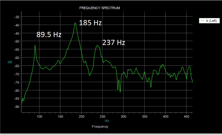
Closed box tap test: air resonance ~87 Hz (T1,1,1), top ~187 Hz (T1,1,2), back ~238 Hz (T1,1,3), cross dipole ~257 Hz. Taps sound good.
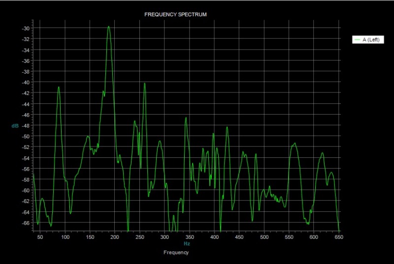
Just-closed tap test: air ~87 Hz, top ~187 Hz, back ~238 Hz, cross dipole ~257 Hz
February 22nd, 2015 — Fretboard Wedge System
One of the most complicated components I've made. With the fretboard glued to the 4mm wedge blank, I routed the upper half of the truss rod slot level to the fretboard (just under it). When the wedge is planed to its final slope, the top slot angle will match the slot in the neck. The wedge extends past the nut end of the fretboard — that excess gets planed flush with the headstock face, becoming part of the headstock so the veneer sits cleanly over it. The fretboard has to be positioned slightly farther from the scarf break than usual to accommodate this.
I was nervous about planing the wedge but the plane was long enough to keep the trailing edge going to nothing in a perfectly straight slope without cutting the leading edge. I made a guide wedge to place in front of the fretboard but I'm not sure it was needed. The truss rod channel in the neck is routed at the reverse slope so the rod stays near the fretboard bottom throughout its full length.
.jpg)
Wedge extension past fretboard end — this excess gets planed to the headstock slope and becomes part of the headstock face
February 28th, 2015 — Neck, Bindings & Neck Angle
With the 4mm wedge on the fretboard I needed a steeper taper on the back of the neck than normal. Rather than using a taper board as the book suggests, I put a 7mm shim at the nut end (3mm for normal taper + 4mm for the wedge) and ran the neck under the Safe-T planer. I finished the bindings and purflings, installed brass inserts and drilled the heel block bolt holes, then bolted the neck on to check center and angle. The body angle was a little more than I'd hoped so I sanded a slight taper onto the fretboard extension to correct it.
Once happy with everything bolted in place I routed the fretboard extension block recess through both the body and the neck tenon. I put a bit of silicone caulk in the truss rod slot and glued the fretboard and wedge assembly down, then planed the excess wedge flush with the headstock face.
.jpg)
Neck thicknessed and profiled — bindings done, ready to carve
March 3rd, 2015 — Headstock Slots
Squared-off headstock slot ramps — first time making them this style. A little nerve-wracking: edges cut with a razor saw, waste carved out with a chisel. Getting the line between the veneer and mahogany looking symmetrical takes some back and forth.
March 10th, 2015 — Padauk CF Bridge
Waiting a few more days for the finish to cure. While waiting I built a contemporary bridge following the Gore/Gilet build volume. I chose Padauk — lighter than rosewood, much lighter than cocobolo, slightly heavier than black walnut, and I wanted the color at the time. I resawed a Padauk strip into 2mm, 3mm and 4mm slices and laminated the stack with two layers of CF sheet using West System 105/206, clamped overnight. The router jig I made for this bridge — aluminium track guides with a well routed by the same tracks — gives a perfectly parallel reference edge for cutting the gap between saddle block and tie block and for routing the saddle.
I shaped the wings with the Luthier's Friend, used the jig to separate the saddle and tie blocks (cut to 2mm from bottom), shaped the saddle with the Luthier's Friend, and cut ledges for bone strips on the tie block. Final weight: 16.5g minus the bone. I'm nervous about the color — it's unusual for a bridge — but with a hint of brown in the shellac it's not too far from the cocobolo headstock veneer.
March 12th, 2015 — Headstock Veneer Redo
Veneer Too ThinWhen I tried to install the tuning machines one tuner on one side sat about half a millimetre above the veneer surface. I remember being proud of my scraper sharpening while thicknessing — turns out I scooped out a bit too much on that side. I thought about leaving it, but finally got the nerve to heat the headstock with my iron, peeled the veneer off cleanly, and glued and shaped a new one. This time I put a black fiber line between the headstock and the new veneer.
March 14th, 2015 — Compensated Nut
Rather than building the full Trevor Gore nut-machining jig (which I didn't have all the parts for yet), I adapted the classical bridge router jig. The Bishop Cochran base adjusts at 0.8mm per turn — so half turn = 0.4mm, quarter = 0.2mm, eighth = 0.1mm — positions easy to see and hit reliably. I made a nut holder the same thickness as the fretboard for depth reference, zeroed on the nut front face, and cut each slot in sequence. All slots came out accurate, a touch over-compensated for clean-up. Because I have a compensated nut, the saddle only needs 0.8mm of compensation — and with a wide classical saddle I have up to 3mm available if needed.
.jpg)
Compensated nut — slightly over-cut for clean-up; with a compensated nut only 0.8mm of saddle compensation needed
March 14th, 2015 — Bridge Placement & Tap Test
Level-sanded and polished the guitar before placing the bridge — ROS at 600 grit, micromesh to 8000, then buff. I measured bridge placement from the 12th fret (the nut edge was cut 2mm shorter for the compensated nut system). With the compensated nut I only need 0.8mm of saddle compensation; the wide classical saddle gives up to 3mm. I checked the plans for locating pin positions, drilled the pins, then outlined the bridge with a new scalpel blade — light cut cleanly through the finish. I scraped the finish off with a heavy-duty utility blade (back end taped so I only track one end), then cleaned edges with a sharp chisel. Blocks taped to the wings for the vacuum clamp, saddle slot duct-taped to eliminate leaks. Eight minutes under the clamp, then clean up squeeze-out and leave clamped for a couple of hours.
Tap test with bridge glued on — top came down ~2 Hz, air resonance up ~2 Hz. Top sits right on F#. Left the bottom brace a bit tall so back can still be adjusted if needed.
.jpg)
Bridge on, neck bolted — starting to look like a guitar
March 22nd, 2015 — Completed & Postmortem
First falcate classical completed. The guitar sounds good and I play it to this day — but I missed the target top frequency. The final top landed around 178 Hz instead of the 190 Hz target, putting the top and air resonance an octave apart at 88.6 Hz. I'm not hearing a horrible weakness around F, but I'm also probably not hearing everything the guitar could have been. The back ended up about 4 semitones away at 224 Hz, which is good.
Postmortem — Brace HeightLooking back at the design assumptions: my falcate SS top was actually 172 Hz, not the 180 Hz I assumed in my relative calculations. If I'd been more careful there, and knowing I wanted to push the classical 20 Hz higher than the SS, I would have kept the braces taller — possibly the full 7mm I use for the SS rather than dropping to 6mm. Good data for the next attempt. I've since built several more falcate classicals using what I learned here.
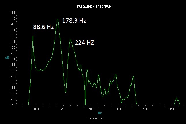
Final tap test with strings — top 178 Hz (target was 190 Hz), air 88.6 Hz (one octave below top), back 224 Hz (~4 semitones from top)
Audio recordings also available on SoundCloud.
First Falcate Classical Guitar
Body ShapeHauser 37 — 12-fret join, venetian cutaway
TopLutz Spruce — 20% thinner than SS target (vibrational stiffness 60)
Back & SidesPanama Rosewood — active back, 10' radius
Top BracingFalcate — CF-reinforced laminated German Spruce, 6mm main braces (vs 7mm SS), 32' radius
Back BracingGore active back pattern — radial lower bout, 10' radius, vacuum box glue-up
BindingsAustralian Blackwood — BWB purfling
RosettePre-made classical mosaic with Australian Blackwood center ring
BridgePadauk — 2-layer CF laminated contemporary design, 16.5g (minus bone)
Headstock VeneerCocobolo — with black fiber line (second attempt after veneer redo)
Neck SystemBolt-on/bolt-off — 4mm fretboard wedge for classical neck angle; truss rod channel with reverse slope through wedge
Top LiningsLaminated mahogany — 4 × 1.8mm plies; fish glue for open time
Back LiningsReverse kerfed
Side WeightsMounts installed — allows post-build top resonance adjustment
NutCompensated — cut with bridge jig / Bishop Cochran base; 0.8mm saddle compensation needed
Pore FillWest System 207 (water-clear hardener)
Final ResonancesAir 88.6 Hz · Top 178 Hz (target 190 Hz) · Back 224 Hz
Build PeriodJanuary – March 2015
.jpg)
.jpg)
.jpg)
.jpg)
.jpg)
.jpg)
.jpg)
.jpg)
.jpg)
.jpg)
.jpg)
.jpg)
.jpg)
.jpg)
.jpg)
.jpg)
.jpg)
.jpg)
.jpg)
.jpg)
.jpg)
.jpg)
.jpg)
.jpg)
.jpg)
.jpg)
.jpg)
.jpg)
.jpg)
.jpg)
.jpg)
.jpg)
.jpg)
.jpg)
.jpg)
.jpg)
.jpg)
.jpg)
.jpg)
.jpg)
.jpg)
.jpg)
.jpg)
.jpg)
.jpg)
.jpg)
.jpg)
.jpg)
.jpg)
.jpg)
.jpg)
.jpg)
.jpg)
.jpg)
.jpg)
.jpg)
.jpg)
.jpg)
.jpg)
.jpg)
.jpg)
.jpg)
.jpg)
.jpg)
.jpg)
.jpg)
.jpg)
.jpg)
.jpg)
.jpg)
.jpg)
.jpg)
.jpg)
.jpg)
.jpg)
.jpg)
.jpg)
.jpg)
.jpg)
.jpg)
.jpg)
.jpg)
.jpg)
.jpg)
.jpg)
.jpg)
.jpg)
.jpg)
.jpg)
.jpg)
.jpg)
.jpg)
.jpg)
.jpg)
.jpg)
.jpg)
.jpg)
.jpg)
.jpg)
.jpg)
.jpg)
.jpg)
.jpg)
.jpg)
.jpg)
.jpg)
.jpg)
.jpg)
.jpg)
.jpg)
.jpg)
.jpg)
.jpg)
.jpg)
.jpg)
.jpg)
.jpg)
.jpg)
.jpg)
.jpg)
.jpg)
.jpg)
.jpg)
.jpg)
.jpg)
.jpg)
.jpg)
.jpg)
.jpg)
.jpg)
.jpg)
.jpg)
.jpg)
.jpg)
.jpg)
.jpg)
.jpg)
.jpg)
.jpg)
.jpg)
.jpg)
.jpg)
.jpg)
.jpg)
.jpg)
.jpg)
.jpg)
.jpg)
.jpg)
.jpg)
.jpg)
.jpg)
.jpg)
.jpg)
.jpg)
.jpg)
.jpg)
.jpg)
.jpg)
.jpg)
.jpg)
.jpg)
.jpg)
.jpg)
.jpg)
.jpg)
.jpg)
.jpg)
.jpg)
.jpg)
.jpg)
.jpg)
.jpg)
.jpg)
.jpg)
.jpg)
.jpg)
.jpg)
.jpg)
.jpg)
.jpg)
.jpg)
.jpg)
.jpg)
.jpg)
.jpg)
.jpg)
.jpg)
.jpg)
.jpg)
.jpg)
.jpg)
.jpg)
.jpg)
.jpg)