Kenneth Michael Guitars est.1978
| KMG "Success Kit" Rim assembly |
The guitar rim is certainly the foundation of a fine guitar. It has to be exceptionally
strong, very rigid and lightweight in addition to providing the exquisite shape for the
instrument. Building a guitar from a kit adds an element of difficulty to the construction
task because the components of the somewhat complex neck joint have been pre-cut.
Because of this feature EXTREME care must be taken to insure that the neck block is in
perfect alignment with the centerlines of the top, back and sides junctions. Also, the
neck block mortise must be perpendicular to the plane of the top edge of the rim.
The design of the KMG kit and associated tools and fixtures allows the builder to
accomplish the above with relative ease.
Prepare the work board by clearly and accurately marking the centerline. Next place a
few strips of clear plastic packaging tape on the work board in the locations
corresponding to the neck and tail blocks
few strips of clear plastic packaging tape on the work board in the locations
corresponding to the neck and tail blocks
Set the mold on the work board with the end joints lined up with centerline. Check to
make sure there is enough tape on the work board to prevent accidentally gluing the
rim blocks to the work board.
make sure there is enough tape on the work board to prevent accidentally gluing the
rim blocks to the work board.
Clearly mark the innermost edge of the waist curves on the mold. The KMG pre-bent
sides are precision formed using this innermost curve as the reference point. Each side
is marked to aide with alignment. This is also a good time to designate this side of the
mold as the back. When removing the rim from the mold it is a good idea to always
keep the same orientation if the rim is place back in the mold.
Place one of the sides in the mold with the top edge down (the top edge is straight).
Place the waist clamp inside the mold in approximate alignment. Align the mark on the
side with the waist mark on the mold. Push the side down so the top edge is flush to the
work board. Tighten the waist clamp. Use a few small clamps to pull the side against the
mold
Place the waist clamp inside the mold in approximate alignment. Align the mark on the
side with the waist mark on the mold. Push the side down so the top edge is flush to the
work board. Tighten the waist clamp. Use a few small clamps to pull the side against the
mold
Use a small triangle or square to
mark the end of the side where it
intersects the work board centerline.
Draw the line all the way across the
side. Make sure the line is absolutely
perpendicular to the work board.
Repeat this procedure on each end
of both sides.
mark the end of the side where it
intersects the work board centerline.
Draw the line all the way across the
side. Make sure the line is absolutely
perpendicular to the work board.
Repeat this procedure on each end
of both sides.
Now the ends of the sides can be
trimmed – we use a band saw.
However, any type of saw can be used.
Strive to just take off the line and keep
the cut as straight as possible. When
placed back in the mold the two halves
should fit snug. It should be noted that
it is not a real concern if the sides do
not fit the mold contour exactly. They
should be symmetrical but slight gaps
are common. If you need to press the
side against the mold simply cut pieces
of 1/8” Masonite slightly longer than
the widths of the upper and lower
bouts. When placed in the mold the
Masonite pieces will wedge the sides in
the mold.
Keep in mind that we are working to make sure the pre-machined cuts are properly
aligned in our rim assembly. To mark the centerline of the machined area place a double
layer of masking tape on the in side top edge of the neck block. Using the truss rod slot
as the reference mark the center on the tape. With a square double-check that the mark
to make sure it lines up with the center of the mortise slot. Note: DO NOT USE THE SIDES
OF THE BLOCK FOR LOCATION PURPOSES, THE CENTERLINE OF THE MORTISE IS
THE CONCERN.
Place the neck block in the proper location and clamp. Using a 1/8” bit, drill a pilot
through the lower (closest to the work board) neck block hole "directly into the
mold". This hole will be used to attach the 3” deck screw and washer clamp assembly.
through the lower (closest to the work board) neck block hole "directly into the
mold". This hole will be used to attach the 3” deck screw and washer clamp assembly.
Its important to always dry fit the assembly, check to make sure everything aligns
properly. Use the waist clamp to keep the sides stable in the mold. Mark the position of
the block on the sides with a sharp pencil. When you are satisfied apply glue to the
neck block (I like (Titebond) and re-clamp. Make sure the block is pressed flat to the
work board. Gradually tighten the clamps and the screw/washer clamp.
Clean the glue off the joint. I use a
popsicle stick sanded to a chisel point.
Check your block location marks once
again. Note how high the block is clear
of the sides – this will be trimmed later.
popsicle stick sanded to a chisel point.
Check your block location marks once
again. Note how high the block is clear
of the sides – this will be trimmed later.
While placement of the tail/end block is not as critical as the neck block, care must be
taken to keep it flush to the top of the rim and on the center line of the work board.
Always dry fit and test clamping arrangement.
taken to keep it flush to the top of the rim and on the center line of the work board.
Always dry fit and test clamping arrangement.
So that conventional clamps can be used
the mold will have to be shifted on the
work board to allow a couple of clamps to
be applied to the topside of the tail block.
the mold will have to be shifted on the
work board to allow a couple of clamps to
be applied to the topside of the tail block.
DO NOT SHIFT THE MOLD UNTIL THE BLOCK HAS BEEN GLUED AND CLAMPED
FROM THE UPPER SIDE OF THE MOLD.
FROM THE UPPER SIDE OF THE MOLD.
Once the block is glued and clamped, make sure it is flush to the work board. Slide the
mold off the work board. Re-clamp the mold to the work board. Position two clamps to
the block from the bottom. Clean the glue squeeze out
mold off the work board. Re-clamp the mold to the work board. Position two clamps to
the block from the bottom. Clean the glue squeeze out
To properly install reverse kerfing an extra step is required in the process. It’s my guess
that’s why more builders are not currently using it. To avoid breakage, in tight curves,
the kerfing needs to be pre-bent. The way I do it is simple, but requires an extra day or
so for the kerfing to dry out. I simply spray the kerfing – on the solid side. Wrap it in
aluminum foil for a few minutes so it gets pliable. Pre-bending is accomplished by using
many clothespins to clamp the kerfing on the OUTSIDE OF THE RIM. This provides
backing to help the solid layer take the shape of the rim. Once its dry remove and
install as normal.
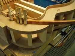
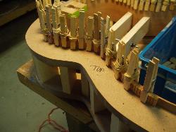
Gluing the pre-shaped kerfing to the rim is straightforward. Spring-loaded clothespins
are simply the best tool for this job – the Martin Factory and many other mass
producers use this method today. We wrap our clothespins with small rubber bands to
generate a little more clamping force. The topside kerfing is glued flush with the top
edge of the side. THE BACK KERFING IS GLUED SLIGHTLY PROUD (HIGH) TO THE
EDGE OF THE SIDES. The high edge will be sanded to match the back contour in a
later operation. We use a small brush to apply a thin NEAT layer of glue on the kerfing
and the sides. Use plenty of clothespins.
ITS A GOOD IDEA TO USE A SMALL MIRROR TO CHECK TO MAKE SURE THE
KERFING IS TIGHT AGAINST THE SIDES AS YOU APPLY THE CLAMPS. Clean Off the
glue squeeze as you progress. Sometimes its best to let the glue dry a little so it peels
off rather than smears.
KERFING IS TIGHT AGAINST THE SIDES AS YOU APPLY THE CLAMPS. Clean Off the
glue squeeze as you progress. Sometimes its best to let the glue dry a little so it peels
off rather than smears.
After the kerfing dries its time to install the rim (1/4 x 1/8) reinforcements. I simply use a
piece of 3x5 card to mark the locations on the rim. I put a reinforcement every 3 inches.
piece of 3x5 card to mark the locations on the rim. I put a reinforcement every 3 inches.
I like to use my digital calipers to pick off the lengths of each of the reinforcements. A
ruler can also be used effectively. Mark each location line with a number and also mark
each corresponding reinforcement.
ruler can also be used effectively. Mark each location line with a number and also mark
each corresponding reinforcement.
Use a razor saw and a mini miter box to cut each reinforcement. Chamfer all the front
edges of the reinforcement – this is a craftsmanship issue.
edges of the reinforcement – this is a craftsmanship issue.
The large spring clamps available at
big box home improvement stores for a
buck each are a good choice for gluing
the reinforcements. Apply a neat light
coat of glue with a brush, place the
piece on the line and secure with a
clamp. Clean up the glue squeeze and
you progress.
big box home improvement stores for a
buck each are a good choice for gluing
the reinforcements. Apply a neat light
coat of glue with a brush, place the
piece on the line and secure with a
clamp. Clean up the glue squeeze and
you progress.
| KMG "Success Kit" Rim Assembly part 2 Top edge contouring |
The next step is unique to our assembly process and fits the scheme of the precision
placement of the neck block. Since glue acts as a very good lubricant prior to its tack
cycle, steps must be taken to prevent the parts from slipping out of place when being
clamped. Not taking action to prevent the neck block from slipping is a common
over sight made by amateur builders (pros too!) and can lead to countless
residual problems as construction progresses
Those using the Mega Mold or Multi-style mold will use the process found
here: ALTERNATIVE RIM ASSEMBLY however it is important to understand the
alignment and part location strategy outlined in this section
here: ALTERNATIVE RIM ASSEMBLY however it is important to understand the
alignment and part location strategy outlined in this section
| KMG kits come with standard triangular kerf linings The slots show on the inside of the guitar no pre-bending required |


