Kenneth Michael Guitars ™
Fitting the neck to the body --- The Basics -- Parts that match


During construction there are several absolutes that affect the fit of the parts at angles
“A” + “B”. I found it helpful to be able to visualize the various angles, contours and
elevations as they relate to the plane made by the top outer edge of the rim.
“A” + “B”. I found it helpful to be able to visualize the various angles, contours and
elevations as they relate to the plane made by the top outer edge of the rim.

Think of the “rim perimeter edge plane” as this imaginary area. It is the flat surface that is
the base for the various angles and projections.
the base for the various angles and projections.


The 89-degree neck angle in my view, works out ideally. Based on measurements I have
taken off Martin factory produced parts, I believe the majority of their products are built
using the same specifications.
taken off Martin factory produced parts, I believe the majority of their products are built
using the same specifications.

In our example of the 89 degrees neck set, we can see how a 40’ radius “X” brace raises the
bridge location to an ideal level. The “top of the fingerboard plane” projects just above the
bridge – string, saddle are at the height required to achieve proper action etc. Note the
effects of a smaller radius “X” brace. These increase the height of the dome raising the level
of the bridge and thus compromising the relationship with the “top of the fingerboard plane”.
Although this is not an article about repair – if I were to encounter this type of mismatch, my
first corrective action would be to make the bridge thinner – I would not try to adjust the neck
angle.
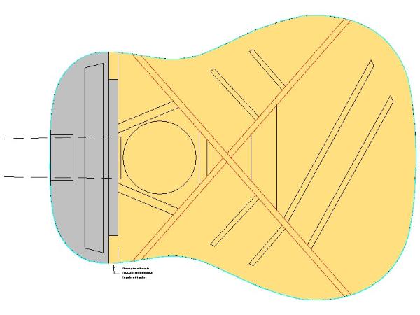
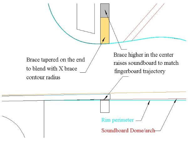
Notice how the “X” brace pattern actually imparts the contour to the soundboard. It is
primarily across the width. A slight amount contour lengthwise and nothing at all in the
(appropriately designated) gray area. The shoulder brace under the fingerboard is
designed with a taper on each end. Because the fingerboard must fit flush to the
soundboard, the center section of the shoulder brace is flat.
The “gray area” is perhaps the biggest mystery to guitar builders, new and old. It is easy to
see that the “gray area” must be angled so that it makes a perfect match with the bottom of
the fingerboard. This is NOT an adjustment issue. The design of the guitar calls for an 89-
degree neck heel/fingerboard angle and a 91-degree rim/ to soundboard angle. Steps must
be taken to build the neck and body to these specifications. What is often overlooked is the
need to raise, or rather, have a rise in the shoulder brace in the center relative to the “plane
of the rim perimeter edge”. If this brace is flat all the way across, the soundboard will be
lowered to the level of the perimeter edge. Consequently, a gap will occur because the “top
to rim” angle has been lost.
With this basic knowledge, a builder should be able plan ahead with the goal to keep tight
tolerances relative to the items mentioned above. Particular attention should be placed on
getting the neck block in perfect relationship to the “rim perimeter edge plane”. It is of value
to know “Exactly” the angle of the neck set machined onto the neck you have purchased.
Even more importantly – before gluing the shoulder brace to the top you must know how
high it rises under the fingerboard area and what angle, that rise creates back to the neck
block at the rim.
In future installments I will detail some additional methods used to assure proper neck angle
set. Elsewhere on the site is a technique for preparing a completed guitar body assembly for
a perfect neck set.
I would like to reiterate that a problem is created when the cheeks of the neck heel are
altered in the effort to get the neck tenon into the block mortise. Carving should only be
done on the tenon. In addition, if the cap created on the mortise by the glued on sides is not
properly and complete removed one cannot expect the neck to fit correctly.
The illustration above shows what we are trying to accomplish. The neck cheek/fingerboard
extension angle, perfectly matches the rim/top angle. The fatal error that I have seen time
and time again is where the cheeks of the neck heel have been trimmed to get the neck into
the body mortises. Doing that changes the neck angle and disregards all the design
parameters --- when that occurs, we are in a major REPAIR MODE --- nothing matches.
The first consideration may seem obvious, but is often overlooked. The combination of “A”
+ “B” is a straight line. If the neck angle is 88.5 degrees and we are trying to match it with a
body designed for a neck with an angle of 89 degrees --- it will not work since the combined
angles do not equal 180 degrees. In the following example, I will use 89 degrees as the neck
angle design criteria. We will explore the relationship of the various top components, their
configuration and how it relates to the neck angle.
I have seen much written regarding the benefits of a radius or contoured top on an acoustic
guitar – dome strength, is one I question, since dome strength relates to the forces from the
outside. The reality is the strings are pulling the instrument apart from inside out. Another, is
sound quality, perhaps? However, I have seen and heard guitars with flat and in some
cases, classic and vintage guitars with concave tops. To me they were so loud and clear
one would swear they were electronically processed. Those discussions will be never
ending. To be sure, the radius on the X brace has a distinct role relative to the neck set
angle. Using the “rim perimeter edge plane” as the reference. One can visualize how the
contour of the brace actually creates a dome and raises the soundboard area were the
bridge is placed.
The following is geared toward the initial construction of the guitar. While aspects of the
information are certainly useful in the repair arena, those corrective procedures will not be
covered at this time.
Because I get inquires, view the various guitar builders forums and fix newly built guitars it
became apparent to me that there is a general mis-understanding regarding the concept
of the neck angle set. For the most part, the problems that are encountered are do to the
fact that the builder has used the terms “neck fit” and “neck set” interchangeably. In other
words, when the necks were installed to the body, most all the surfaces on the neck joint
have been trimmed to make the connection cosmetically acceptable. Unfortunately,
doing this completely disregards all the mathematical requirements needed to build the
instruments as designed.
I hope that the following will clarify why certain dimensions must be held to very close
tolerances during the construction processes. The proper connection between the neck
and body is not by accident --- there is no “magic fairy dust” used by the seasoned luthier
to get this correct. The key is understanding the design criteria, good planning and
accurate measuring and execution in the initial building stages.
Even though we are attempting to impart the “hand made” appeal to our works, trying to
emulate some of the mass production mentality can only lead to better quality and
improved efficiency. The example I will sight is the fact that the necks and the guitar
bodies for the same finished instruments are built by different individuals. In fact, in
different locations in the factories. Nevertheless, when the time comes the necks and
bodies are assembled perfectly in a relatively short period. The reason this is possible is
that the parts “were made for one another”.
Neck Set Angle
Myth, Magic or Mathematics?
© K. M Cierpilowski
Myth, Magic or Mathematics?
© K. M Cierpilowski
NOTE: I have contacted Steward-MacDonald - they indicated 90 degres is
normal. Unfortunately, their customers report a range of different angles. So
the assumption is SM guitar necks ARE NOT precision machined to a set angle.
For what ever reason it is left up to the builder to HAND CARVE the cheek
angle then repair and shim the tenon.
normal. Unfortunately, their customers report a range of different angles. So
the assumption is SM guitar necks ARE NOT precision machined to a set angle.
For what ever reason it is left up to the builder to HAND CARVE the cheek
angle then repair and shim the tenon.
OK – much information, many variables. Again, what we can see from the drawings is that
the top plate, under the fingerboard extension is higher than the perimeter edge of the top.
So there is a construction theory that dictates the creation of a dome or bulge. To
complicate matters – the bulge has to be flat on the very top (the bottom of the fingerboard
is flat). Also, the shoulder brace has to rise in the center and intersect the angle made by
the bottom of the fingerboard extension. The contour of the shoulder brace does not
necessarily match the contour of the “X” braces --- it’s the height of the brace under the
fingerboard that matters not a curve/contour dimension issue.
The instructions for one of the popular kits calls for the fabrication of an angled sanding
stick. Since the unfinished and un-sized rim is used for the position locator it is virtually
impossible to sand any dimension in an accurate manner. If you don’t know where you
started how can you possibly know when and where you finished? Machining operations
must have a true “starting position” so you can remove a certain amount of material based
on subtracting the amount removed from the starting SIZE.
Another school of thought calls for sanding angles on the top edge of the rim and neck
block using a contoured sanding bar or a contoured dish covered with sand paper. While
these methods work OK for the back of the rim, they create a new problem when machining
the top edge. Remember the top of the neck block MUST BE FLAT, using a contoured
sanding device creates a domed surface in both directions --- exactly what we want on the
back of the rim. However, doming the top of the neck block and the center of the lower bout
area is undesirable and will cause a hump under the fingerboard extension. Now, its true the
hump can be sanded flat again --- but since the top section (apex) of the dome is the
dimension/location we were seeking, once it is sanded flat the top of the neck block is lower
then desired.
Now it goes without saying that many guitars have indeed been constructed using the above
theories and methods. The problem is that these methods have inherent processing flaws
and are likely to cause dimensional errors. The construction manuals for the two prominent
kits are unabashed in their knowledge of this situation as they both have fairly complete and
extremely complicated sections detailing how to RE-CARVE the neck joint CHEEKS and all
to customize it to fit the body that has been constructed. Unfortunately, there are a fair
amount of failures as well, as evidenced by struggling builders posting in desperation on the
various forums. Many not so complete kit guitars are also available on the Internet auctions.
So what is the alternate?
The top of the line guitar producers including Martin, Larrivee, and many others take a
different yet very simple approach to solving the neck set geometric problem. The light
goes on for many when viewing the following video of Chris Thomas' Martin factory tour.
The focus of this discussion is located in Part 2 near the beginning. He clearly states
contoured dish for the back and flat sanding for the top edge. Please take time to view the
clip. Chris Thomas
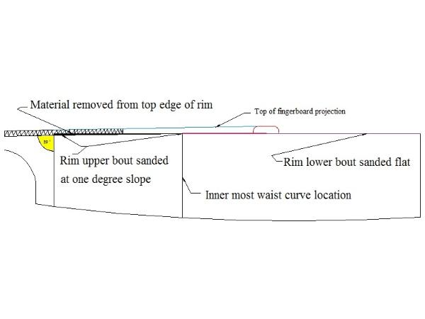
The top edge of the rim is sanded flat from the tail block to the edge of the
gray area mentioned above, than slopes down to form the required
complimentary angle to match the neck heel, this results in the straight line
fingerboard plane.
The top of the line guitar producers including Martin, Larrivee, and many others take a
different yet very simple approach to solving the neck set geometric problem. The light
goes on for many when viewing the following video of Chris Thomas' Martin factory tour.
The focus of this discussion is located in Part 2 near the beginning. He clearly states
contoured dish for the back and flat sanding for the top edge. Please take time to view the
clip. Chris Thomas
The top edge of the rim is sanded flat from the tail block to the edge of the
gray area mentioned above, than slopes down to form the required
complimentary angle to match the neck heel, this results in the straight line
fingerboard plane.
HOW SIMPLE IS THAT!!! Instead of raising the soundboard under the fingerboard extension,
the neck joint is actually lowered slightly relative to the top edge of the rim. As described by
Dick Boak all that is required is to sand a slope on the top edge at an angle from the waist
curve to the neck block. In effect the top plate has a tiny, invisible bend starting at the waist
curve. Based on countless measurements and quality checks I have determined that in reality
the slope angle is just slightly over one degree.
The KMG "Success kit" uses this rim sloping strategy -- take a look here to see how we
accomplish this using the provided tools and fixtures. With an understanding of the goal and
process, I am sure there are many other methods that could be used to get the rim
sloped/tapered to the correct neck set angle. Our state of the art Mega Mold can also easily
and accurately create the top edge slope and back edge contour.

| Here's the actual Martin Factory process -- the rim is placed in the profile jig with the top edge slightly proud |


| The sander has a perfectly flat sanding plate |
The entire sound-board edge is sanded perfectly
flat at a 90 degree angle to the sides and blocks
flat at a 90 degree angle to the sides and blocks
Finally the pneumatic arms on the machine tip the rim
1.3 degrees sanding a flat slope from the "upper bout"
sound hole location to the neck block
1.3 degrees sanding a flat slope from the "upper bout"
sound hole location to the neck block
That's it ---- no contour dish involved in the rim sound board edge
process -- a myth that is prevalent among hobbyists and pro's especially
on the Internet. With the dawn of cutaway acoustic guitar makers could
no longer sell instruments that humped at the neck joint and were not
playable on the fingerboard extension. This process assures the straight
line finger board plane described above. Jim Olson and Charles Hoffman
use a router to shave the rim to create the slope.